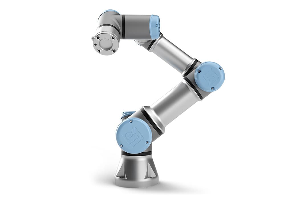
Autonomous Manipulation Pipeline
6-DOF Robotic Arm · Perception · Kinematics · Control
This project was the final deliverable for ENME480, a robotics course at the University of Maryland, completed in Fall 2025. The objective was to design and implement a complete autonomous manipulation pipeline for a 6-DOF industrial robotic arm — a system that could detect colored geometric blocks placed at arbitrary locations on a workspace, compute the joint trajectories needed to reach them, and stack them at defined target positions, entirely without human input. Every layer of the robotics stack was built from scratch: camera calibration, perception, coordinate frame transformation, forward and inverse kinematics, control, and system integration.
Rather than treating each component as an independent module, the pipeline was designed for coherence — decisions in the kinematic model had to align precisely with what the controller expected, which had to match exactly what the perception system was outputting in the robot's coordinate frame. That end-to-end consistency is what made physical deployment straightforward: the same codebase that ran in Gazebo simulation deployed to the physical arm without modification.
The final system ran as a modular, multi-node ROS2 architecture written in Python, containerized in Docker, and validated in Gazebo before hardware deployment. On the physical UR3e, the pipeline autonomously detected ArUco-marked blocks, resolved their positions into the robot's base frame via perspective homography, solved the inverse kinematics analytically, and executed pick-and-place sequences — achieving positioning accuracy within 2–5 mm across all validated configurations.
Pipeline Architecture
Five functional stages from raw camera input to physical arm execution — each with a defined input/output contract, independently testable and replaceable.
01
Camera Calibration
Intrinsics · Homography H
Camera intrinsics and distortion coefficients from YAML calibration. Perspective matrix H computed from 4 reference point correspondences.
02
ArUco Detection
OpenCV · Marker Pose · Pixel Centers
ArUco fiducial markers detected in each frame. Four corner points extracted per marker; center computed by averaging corners.
03
Frame Transform
Homography · Image → Table
Pixel center multiplied through H and normalized by w to yield physical (X, Y) in the table coordinate frame in millimeters.
04
IK Solver
DH Parameters · Law of Cosines
Closed-form analytical solution for elbow-up configuration. Six joint angles computed in seven sequential steps from world-frame target pose.
05
Arm Execution
ROS2 · Gazebo → UR3e
CommandUR3e messages published over ROS2. Nine-step motion sequence: lift, transit, descend, grasp, lift, transit, place, release, lift.
Technical Breakdown
The full implementation — one layer at a time.
01
Camera Calibration & Perspective Mapping
Camera intrinsic parameters and distortion coefficients were loaded from a calibration YAML file produced during checkerboard calibration. A perspective homography matrix H was computed by clicking four known reference points on the live camera feed and mapping them to their corresponding real-world table coordinates in millimeters. This 3×3 matrix encodes the full projective transformation from image space to table space — applied every frame by multiplying each detected marker center's homogeneous pixel coordinates through H and dividing by the resulting w-component to recover physical (X, Y) position in millimeters.
02
ArUco Marker Detection
OpenCV's ArUco library detects fiducial markers attached to the colored geometric blocks in every camera frame. For each detected marker, the four corner pixel coordinates are extracted, the center is computed by averaging them, and the marker ID is confirmed against the DICT_6X6_250 dictionary. The annotated frame is published as a ROS2 image topic for visualization, while detected marker IDs and image-space centers are passed downstream for coordinate transformation.
03
Forward & Inverse Kinematics
The UR3e was modeled using Denavit–Hartenberg parameters across seven link transforms, building a forward kinematics function that returns the full 4×4 SE(3) homogeneous transformation from base to end-effector for any joint configuration. Inverse kinematics were solved analytically for an elbow-up configuration: θ₁ from polar geometry and a lateral offset correction, θ₆ from yaw and θ₁, the wrist center from a fixed distal offset, and θ₂/θ₃/θ₄ from the law of cosines applied to the two-link elbow triangle. Predicted and physically measured end-effector positions matched within 2–5 mm across all test cases.
04
Singularity Handling & Joint Safety
The IK implementation explicitly handles two singularity classes: configurations where the wrist center falls directly over the base Z-axis — causing a divide-by-zero in θ₁ — and configurations outside the physical workspace. Joint angle limits are enforced at the publisher level. The system resets to a predefined safe home configuration when a dangerous joint state is detected, and both singularity types are excluded from the operating workspace through validated coordinate bounds.
05
ROS2 Architecture & Deployment
All components run as decoupled nodes in a ROS2 architecture: an ArucoTracker node handling perception and coordinate publishing, a UR3eController node managing joint commands, gripper state, and position feedback via the /ur3e/command and /ur3e/position topics, and a BlockMover node orchestrating the complete pick-and-place sequence. Nodes communicate over defined typed ROS2 topics, keeping each layer independently replaceable. The full system was containerized in Docker and validated end-to-end in Gazebo before deployment on the physical UR3e, where it ran the complete detection-to-stacking sequence autonomously.
Simulation & Hardware
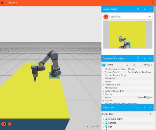
Gazebo Simulation
Full pipeline validated in simulation — same codebase, Docker container, and ROS2 node graph. No code changes required for hardware transfer.
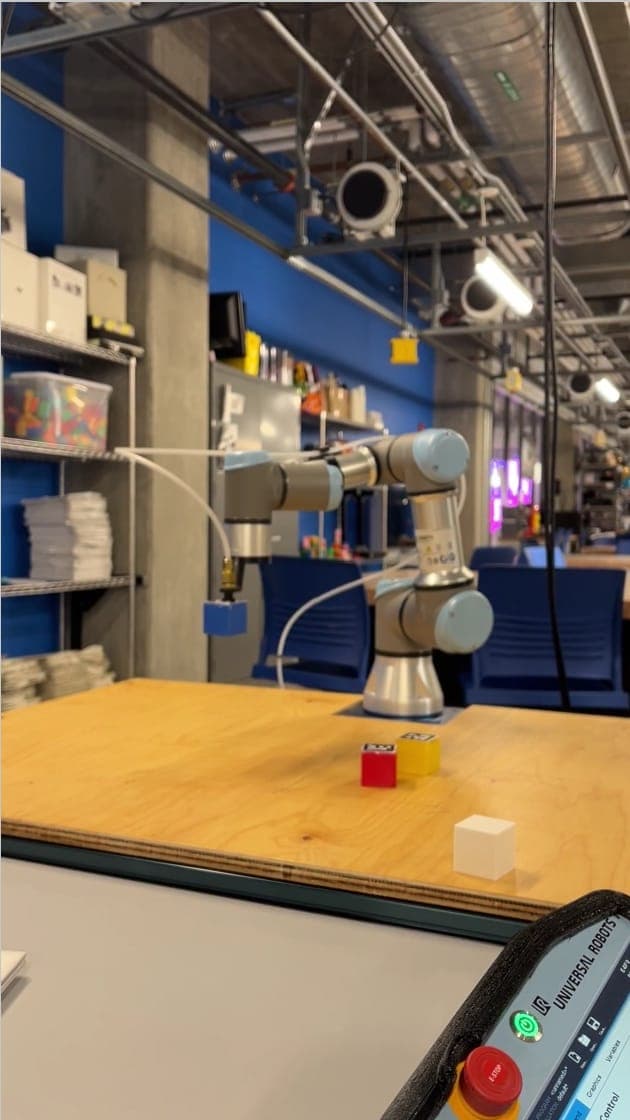
Physical UR3e
Universal Robots UR3e — autonomous ArUco detection, IK solving, and sequential block stacking at millimeter-level accuracy.
The Docker containerization ensured the ROS2 node graph, kinematic solvers, and perception pipeline ran identically in simulation and on hardware. Validation in Gazebo exposed edge cases in the joint safety checks and singularity handling before they could cause hardware faults. On the physical UR3e, the complete pick-and-place sequence ran without human intervention — detecting blocks, computing trajectories, and stacking them at defined positions in sequence.
Validation Results
Inverse kinematics validated across five physical test cases on the UR3e.
Discrepancies attributed to link length tolerances, joint backlash, and manual grid measurement uncertainty of ±1–2 mm.
Stack
My Documents
Technical report, demo videos, and supplementary materials from ENME480 Fall 2025.
Technical Report
Autonomous Manipulation Pipeline
15-page formal report covering the full derivation: SE(3) transforms, DH parameters, analytical IK, perspective homography, ROS2 architecture, and validated results.
Google Drive
VIDEODemo Video
ArUco Detection Pipeline
Live camera feed demonstrating real-time ArUco marker detection, coordinate overlay, and perspective homography transform to table frame coordinates.
Google Drive
VIDEODemo Video
Full Pick & Place Demo
Complete autonomous pipeline on the physical UR3e — block detection, IK solving, and sequential pick-and-place stacking executed without human input.
Gallery
ENME480 · Fall 2025 · University of Maryland
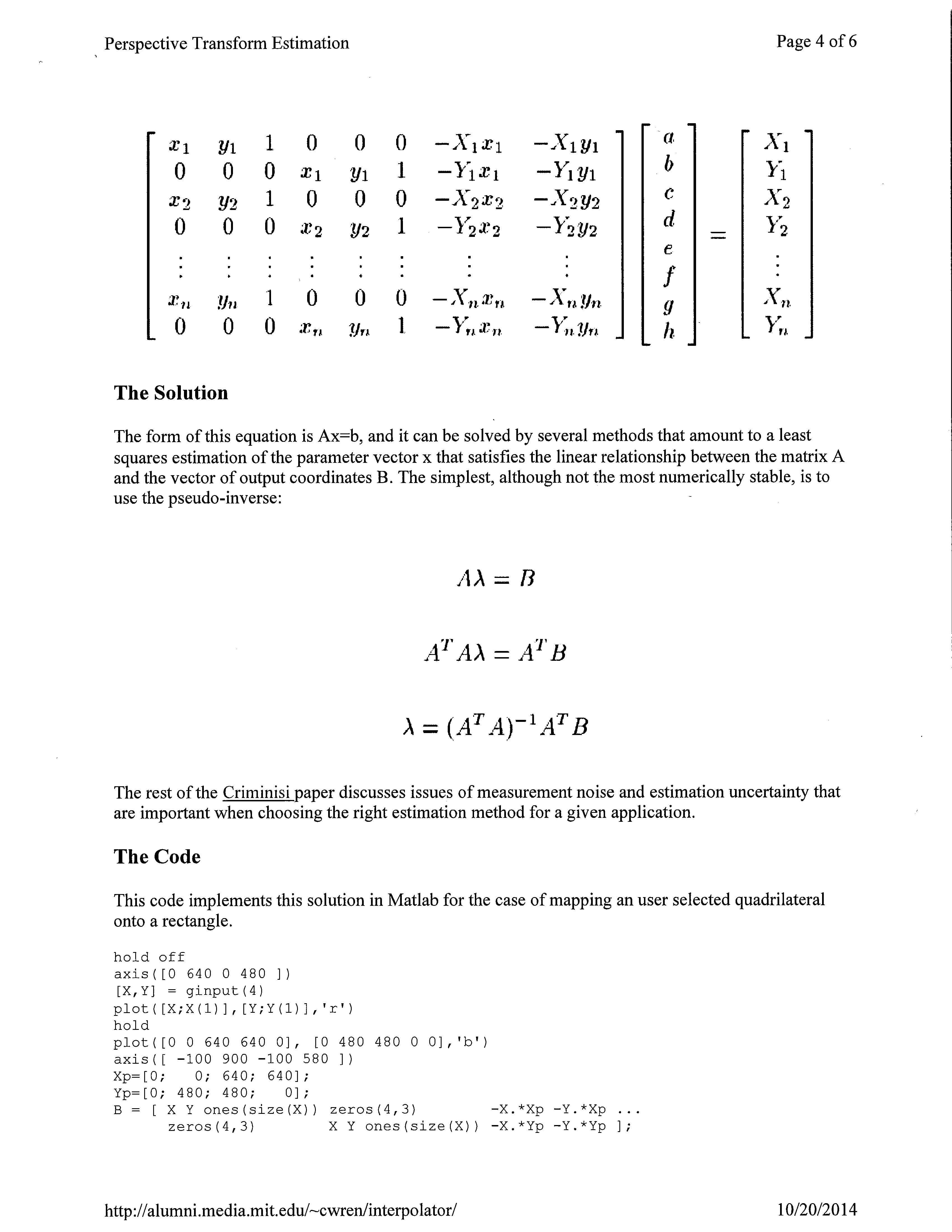
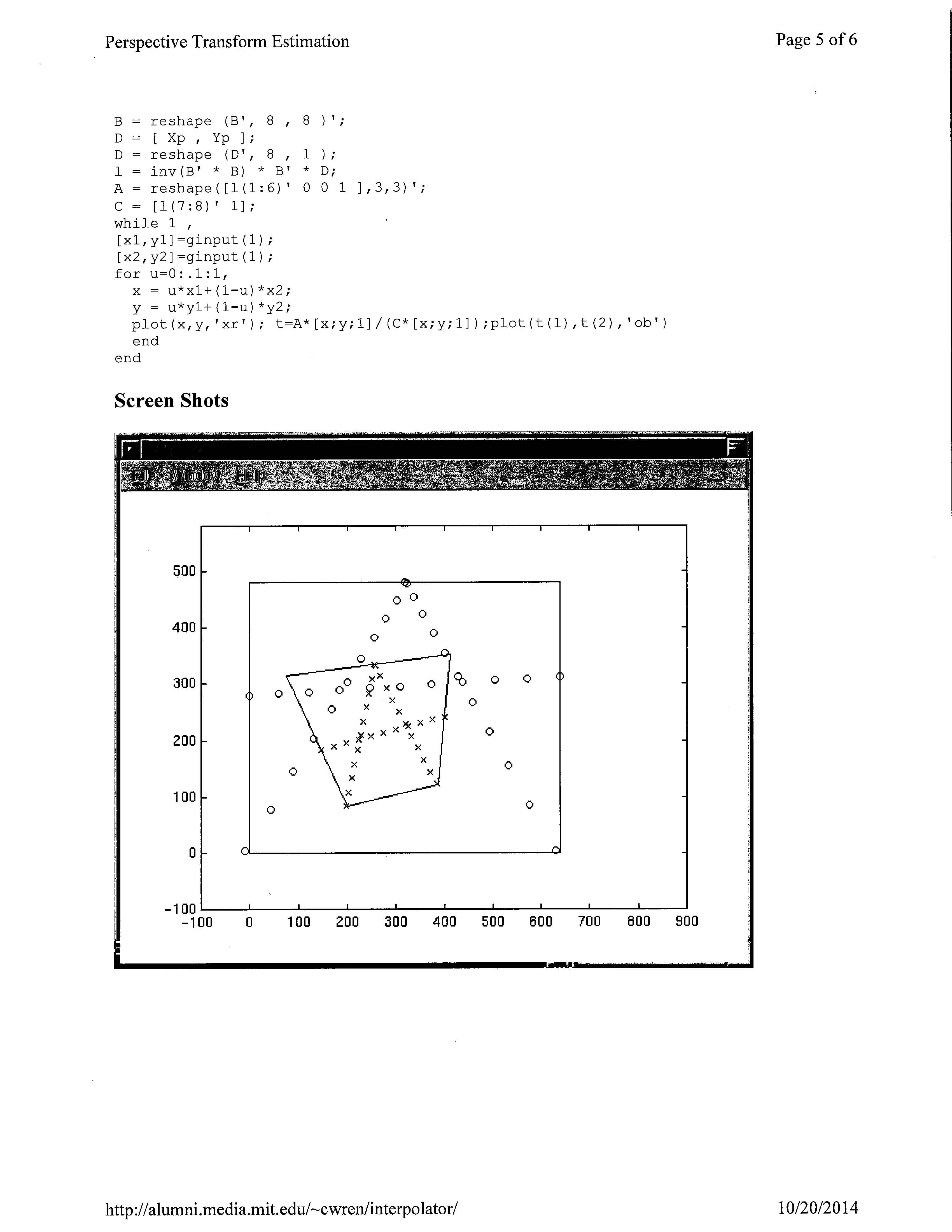
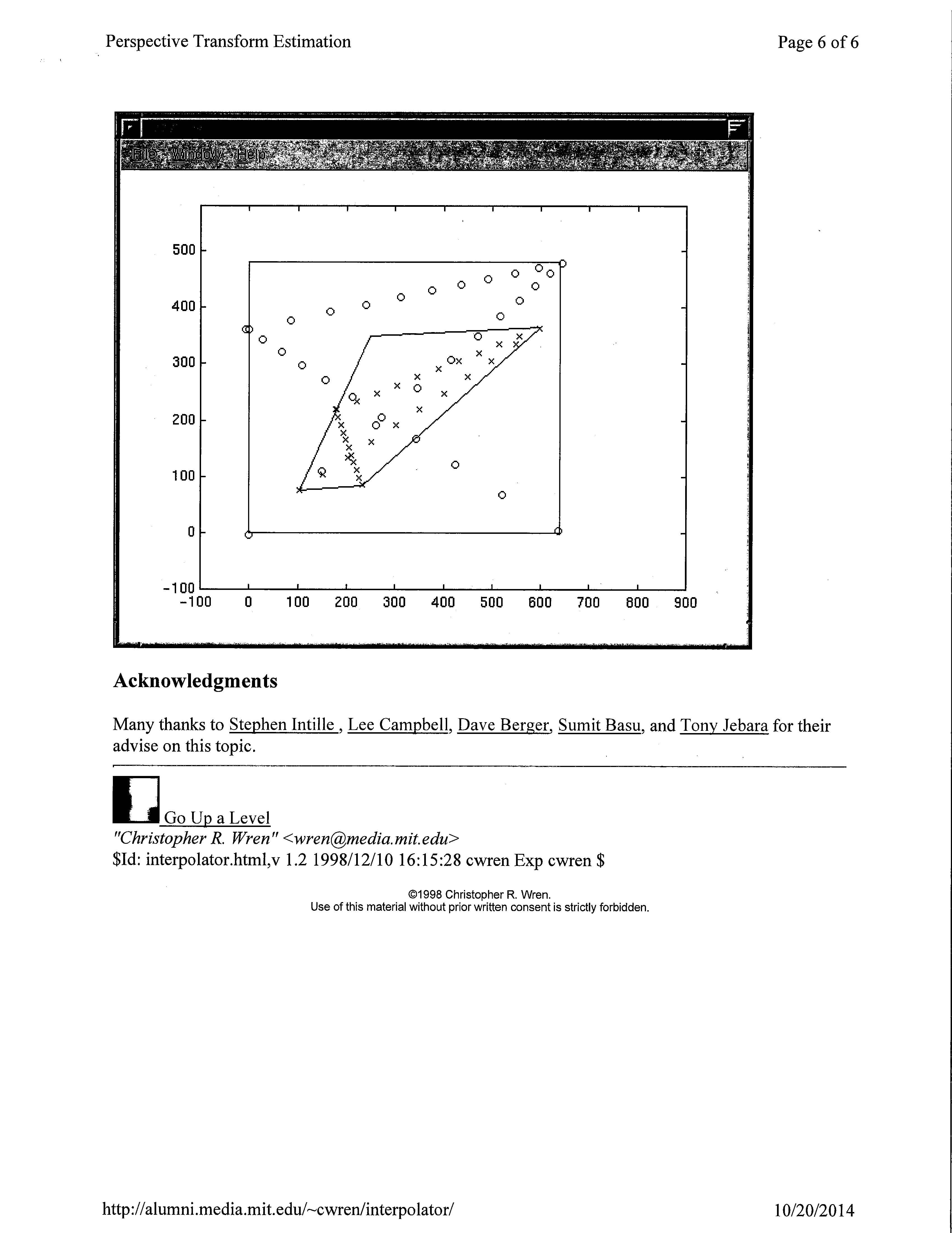
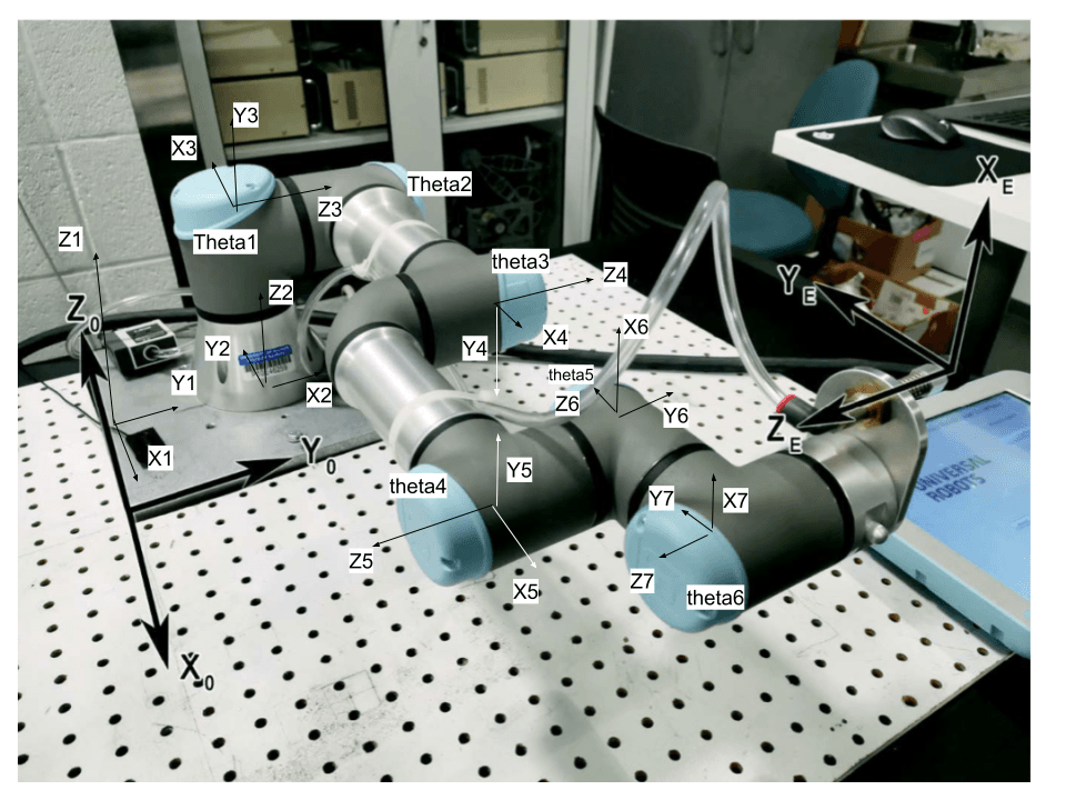
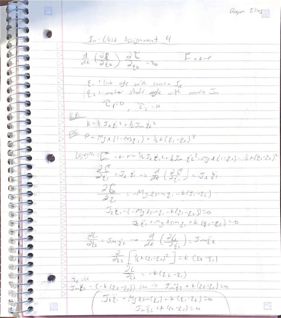
Captures from the project demo and hardware validation — Gazebo simulation, UR3e test setup, and perspective homography visualization. Click any image to enlarge.